Discount Code: ECOPOWER at EcoFlow.com
Powering Home Circuits
Manual options to full automation
Guest writer Mark Hicks (a.k.a. EcoPower)
This article focuses on powering North American 120v single phase and split phase home circuits. Although the concepts may be transferrable to international 240v single phase circuits, this is outside the author's area of expertise and international versions of EcoFlow products may operate differently.

There are a lot of questions, confusions, opinions, and ideas (both creative and dangerous) when it comes to powering home circuits with a power station. Let’s discuss two main use cases and explore the primary products and tactics for them.
Backup Only
The purpose and scope here is only to provide power to home circuits, if and when the grid goes down. This can apply to those with or without grid-tied solar and can be accomplished with or without off-grid solar. Using off-grid solar might take the form of a small array that keeps the batteries topped up ready for an outage, or a few portable or temporary panels hauled out when and if an outage occurs. Without off-grid solar, batteries are only maintained using AC (from the grid or, possibly, a grid-tied solar array).
Load Shifting
Charging batteries during off-peak hours and powering home circuits during on-peak hours, as well as charging with solar during the day (perhaps while powering home circuits from battery at the same time), and using stored solar power at night, are all examples of “load shifting”. Once again, this applies both to those with and without grid-tied solar and may or may not utilize off-grid solar.
Hybrid
Using solar with emphasis on storing power for an outage (while still doing some load shifting), as well as cycling with solar daily, part of the year, and only using solar for backup storage during periods of poor solar production, or when there is high potential for power outages, are examples of hybrid use cases (“both and” vs “either or”).
Manual Backup Solutions
Individual devices or appliances can be plugged into any of the Ecoflow Delta Series power stations and, using a properly wired single phase manual transfer switch, any of them can be connected to power a few home circuits. While the following applies, in general, to any Delta power station, our main focus, for home circuit connection, will be the DELTA Pro (DP) and DELTA Pro Ultra (DPU).
Power Station Only

Plugging various appliances into a DP or DPU and powering them with battery in an outage is simple and straightforward. Adding solar to provide battery charging can become a bit more involved, depending on the scope… Plugging them into an AC wall outlet to operate in EPS mode is where we get into caveats.
The DELTA Pro supports direct pass-thru of AC input to loads while charging but because the input can only handle 15A the maximum for loads plus charging is limited to 1800W. The charge rate will ramp down in favor of loads but this mode can also be prone to overload if there is a sudden increase in load demand while the battery is already being charged at high rate. The secret to the 1800W fast charge capability of the DP is the inverter used “in reverse” for AC charging but this is also where the limitations lie, as the inverter cannot charge and discharge at the same time.

The Delta Pro Ultra has 2 single phase inverters, under the covers, and is ‘similar’ to 2 x DP (integrated into one unit with one battery bank) in that it supports pass-thru, the inverters are used for AC charging (and cannot discharge while charging), and AC input is limited to 15A (on the 120V input). However, the output limitations of the DP are overcome by DPU in that, when load demand exceeds input, the inverters will actually augment the input to satisfy load. This means the full 3600W per inverter (7200W @ 240V) is available to AC loads while “charging”. In reality, when load demand exceeds available input, there is no charging going on at all. For example, 3000W of output with 1000W input means the inverter(s) are not ‘charging’ but instead ‘discharging’ 2000W from the battery to make up the difference. This is ‘similar’ to charging the battery at 1000W from solar while discharging 2000W via the AC inverter(s) in terms of the rate at which the battery is depleted.

In addition to the above, the DPU has two “UPS modes”. They are “Backup UPS” (similar to “EPS” mode on DP with a 20ms switching time) and “Online UPS” (0ms switch time with loads always on battery). The Online UPS mode applies only for 120V loads on the 3 designated outputs and only with 120V AC via the 15A C20 input. This is accomplished by using one inverter to charge the battery (if/as needed) and the other inverter to power loads from battery, thus, no switch time. For 240V split phase output, or when using 240V split phase input (via the 30A generator input adapter, for example), only “Backup UPS” (20ms) mode is available for all AC ports.
Manual Transfer Switch

Using a Manual Transfer Switch (MTS), individual home circuits can be wired such that each can be switched between grid and alternate (external) power sources (such as a generator or battery power station). A gas generator can be connected to a power station while the power station is connected to MTS (keeping in mind the pass-thru limits for DP). However, while connected to MTS, a power station must never be connected to AC input from a wall outlet in the home. Plugging any Delta power station into a wall outlet while connected to an MTS can damage the power station, potentially energize the metal on the MTS itself, and lead to other unpredictable (and potentially dangerous) conditions. This is a case where “even if it works, it’s not right, prudent, or safe” and is a clear violation of national electric code. Just don’t do it, okay? Please?
Single Phase vs Split Phase

When it comes to MTS there are single phase 120V and split phase 240V options. With a single DP, single phase is the ONLY option. DPU can be used with single or split phase MTS but 2 DP, paired via the Double Voltage Hub (DVH), are required to accommodate split phase. Single phase means only connecting 120V circuits that do not share a neutral with another 120V circuit (what is referred to as a Multi Wire Branch Circuit, or MWBC). If you don’t know what an MWBC is or how to identify them please engage a professional to assess your circuits and clarify options before installing a single-phase MTS. A split phase 240V MTS can support both 120V circuits (including MWBC) and 240V circuits. Note: 2 DP, plugged into the DVH, cannot be AC charged while the DVH is in use.
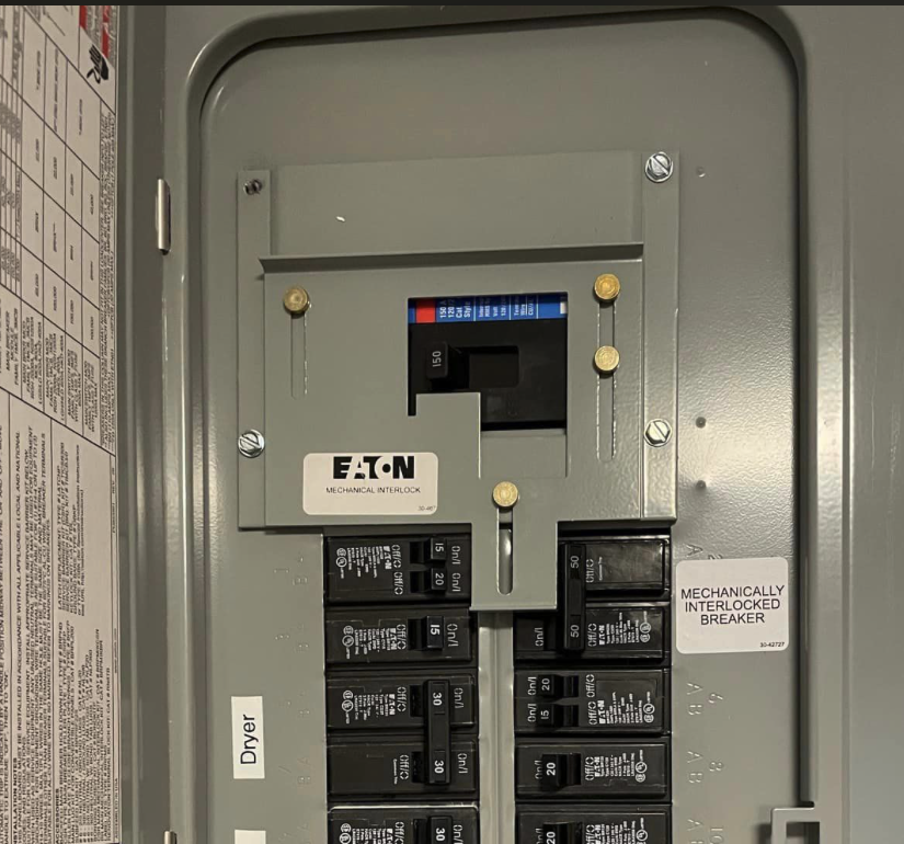
Main Panel Interlock

Photo Credit: Kevin Mui @ EcoFlow DELTA Facebook Group
Some jurisdictions allow (and some home owners may already have) a generator back feed breaker that uses a mechanical interlock with the main breaker such that only one or the other, and never both, can be on at any time. This setup is split phase by design which means a single DP is not an option. Adapting a single-phase power source, be it 120V gas generator or power station, to bridge both phases in the main panel (or an MTS) is not only a bad idea it is potentially quite dangerous and a clear violation of the national electric code. Again, please, just don’t do it!
Technically, an un-bridged adapter could theoretically be used to supply power to one phase (half the circuits) in the main panel (or MTS) but that is prone to issues as well. Get it done right by implementing a properly wired single phase MTS or using a split phase power source!
Automated Backup Solutions
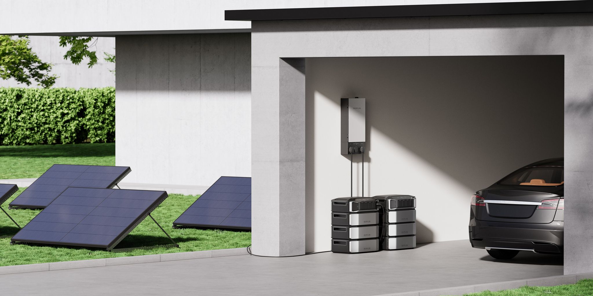
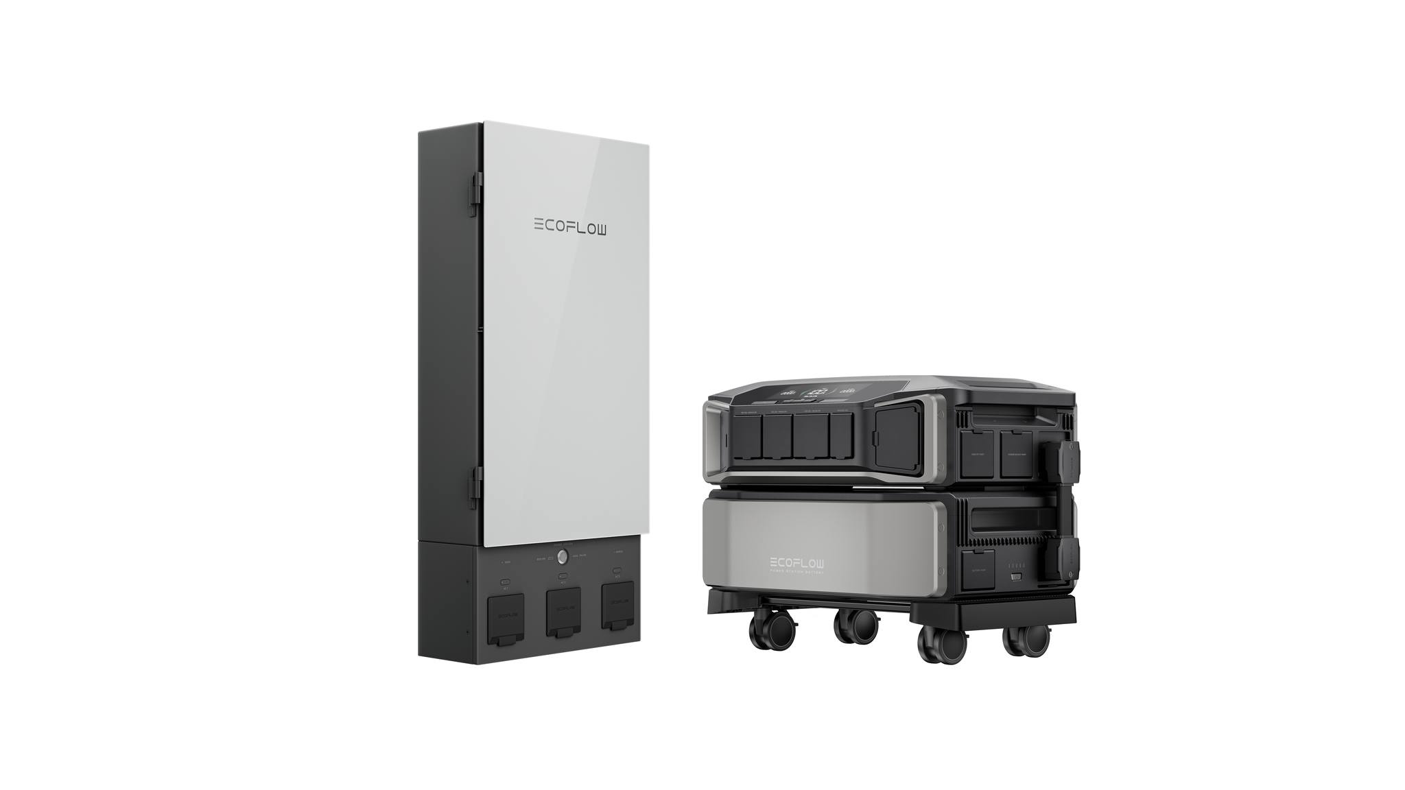
While a manual transfer switch is fine for Backup Only scenarios, Load Shifting and Hybrid use cases tend to require a more automated approach. The Ecoflow solution for this is the Smart Home Panel (SHP). While there are “creative workarounds” (Switched Mode Power Supply or specialized transformer for example) that can potentially create a “pseudo-EPS” for home circuits without the SHP (and without creating a dangerous wiring situation) the fact is each of them have costs and tradeoffs that can quickly close the gap against the price of SHP (not to mention that none of these solutions can provide the automation or programmable settings of the SHP).
Smart Home Panel 1

The SHP1 is an “electronically controlled automatic load side transfer switch”. It supports a maximum of 30A per circuit relay and up to 7200W max from battery (using 2 x DPs). In single phase configuration, it accommodates up to 10 x 120V (non-MWBC) circuits using either 1 or 2 DP. It also supports 1 or 2 Power Kit (PK) Hubs, but we won’t go into that product in this article. In split phase configuration, it supports up to 5 x 240V circuits or a combination of 120V (including MWBC) and 240V circuits with each 240V (or pair of 120V MWBC) circuit requiring two relays (one on each phase) and those each need to be ‘linked’ in the split phase settings of the SHP1 app. Split phase mode requires 2 DP (or 2 PK). The SHP1 is ETL certified for use in the USA (but not in Canada, unfortunately).
The SHP1 has a built-in power outage automation where the user can choose which circuits to power in an outage and set a priority for circuits to be shed if load gets too high while running on battery in an outage. The user can also create schedule-based automations for charging batteries from the grid and for switching circuits to battery (for load shifting and/or solar consumption, for example). Other settings include EPS mode (which keeps the inverters online at all times to facilitate 20ms switching in an unexpected outage, but also depletes batteries faster on standby), charge and discharge limits, naming circuits, etc. and includes some limited logging and power usage history. Perhaps the most unique feature of the SHP1 is that, because it is a load side “transfer switch” with a relay on each circuit that can source power from grid or battery, the user can choose to have certain circuits run from grid while others run from battery at the same time. To use my own configuration as an anecdote: My summer configuration, aimed at maximizing solar ‘self-consumption’, consists of two separate automations. One runs 24x7 switching 6 circuits in the basement to battery anytime there is enough battery to support it. The other switches the 4 circuits upstairs to battery only during peak solar hours.
Smart Home Panel 2

The SHP2 is a sub panel with 100A feed from grid and 90A feed from battery. It has a main relay that can switch the entire panel between grid and battery and branch circuit relays that can turn a given circuit on or off. Unlike the SHP1, it cannot support having part of the circuits on battery while the rest remain on grid as the entire panel must be supplied by one or the other. It supports 12 circuits, with a maximum of 60A per circuit, and up to 21kW max from battery (using 3 x DPU). It is a split phase configuration that supports all 120V and 240V circuits (up to 60A) and can be used with 2xDP (via the Double Voltage Hub 2 adapter), a combination of 2xDP and 1 or 2 DPU, or 1-3 DPU. The panel accepts a variety of standard circuit breakers including tandem and quad as well as AFCI and GFCI breakers. In many cases, branch circuit breakers from the main panel can be moved into SHP2 without the need of new breakers. The SHP2 also has a slot for a 30A2P or 50A2P back feed breaker that can be wired to an appropriate inlet for use with a gas generator and includes a mechanical interlock to switch the non-battery feed between grid and generator. As with SHP1, any 240V or MWBC circuits need to be ‘linked’ in split phase settings within the app.
The SHP2 has outage strategy settings that allow the user to specify circuits that need to always be powered when grid is down, vs those to power only while battery is above a set percentage, vs those not to power in an outage. Like SHP1, schedule-based automations for charging batteries from grid and switching circuits to battery can be created. New with SHP2, are additional modes for Time of Use (charge/discharge based on energy cost), Self-Powered Mode (always run from battery if available), Backup Reserve (stay on grid below set percentage, except in outage), and Storm Guard (charge batteries to 100% when a storm is expected). The Self-Powered Mode is perfect for simple, easy, solar ‘self-consumption’. Another feature, unique to SHP2, is alternate output and charge rate limits for use with a generator. These take effect when the generator back feed interlock is engaged.
Delta Pro vs. Delta Pro Ultra

If home circuit connections require split phase, unless there is an existing investment in Delta Pro, the Ultra is the clear choice. It is superior to using two DP with Double Voltage Hub (DVH) to achieve split phase in almost every way. While a set of 2 DP has more total battery storage (7.2kWh vs 6.1kWh), the batteries on each DP will not deplete in unison when loads on different phases are not equal. This is often the case as 120V loads must be placed on one phase or the other and, once one battery is depleted, split phase output is terminated, no matter how much capacity might be left in the second battery. In addition, the inverters on DPU have a superior design with better power management and stronger tolerance for surges and, unlike 2DP + DVH, 120V input can be supplied while providing split phase output (as long as it is not supplied from a house outlet while DPU is connected to a manual transfer switch). For single phase applications, the DP can often be the more economical choice and, for those already invested in the DP, it’s still a solid solution, fully compatible with the new SHP2, and can co-operate with 1 or 2 DPU when connected to SHP2 using the new DVH2 Power I/O adapter.